LA0BY,
last updated 16.09.2000
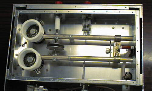
View of anode circuit
| Description
of a 144 MHz high power amplifier for 2 x 4CX250B
LA0BY,
last updated 16.09.2000
View of anode circuit |
|
This page provides information on the design and practical implementation of an inexpensive 144 MHz high power amplifier using a pair of ceramic tetrodes, type 4CX250B, in a push-pull configuration. The amplifier has been built in many variations. I have used it mainly for MS and EME operation for many years.
Important design features and measured operating parameters are displayed in the manual (WfW 2.0, 21 kB). The schematic diagrams were originally drawn by Designer 3.1. In order to make them come out independently, the drawings were exported into GIF and JPEG format. Those may be imported into Word documents and printed with reasonable, but not perfect quality.
Schematic diagramsNEW: Construction drawings made by OM1CW in Word 6.0 format.Switching and metering circuits: GIF 13 kB, JPEG 57 kB